A little ‘Low Relief’

Well having built got so many of these laser cut models from https://www.lasercutrailwaymodels.co.uk/O-Gauge-7mm, I’m starting to feel that I need to make some more progress with the factory units.

They really are good value and go together really well and I would certainly recommend them to anyone.

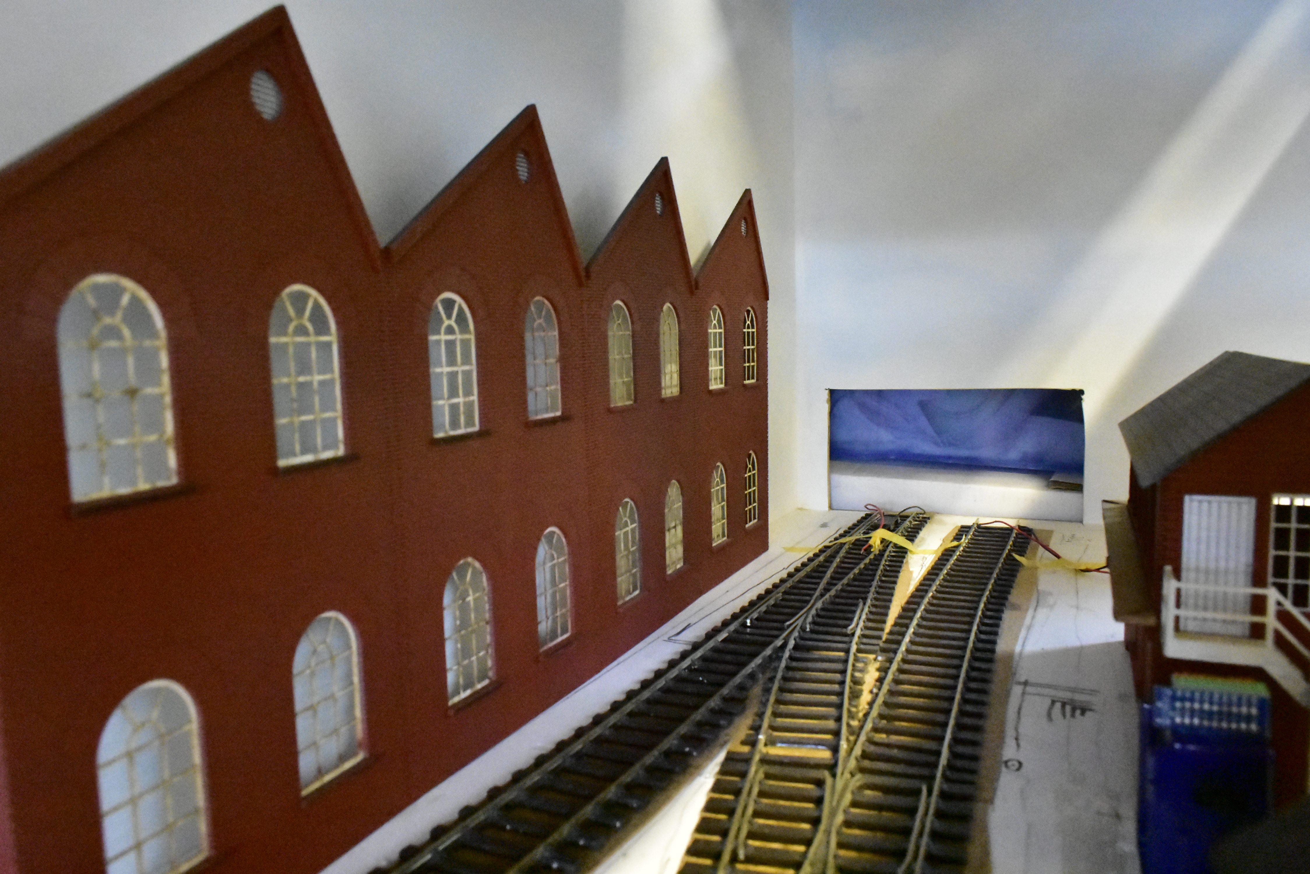
The factory units shown below where built around the country in vast quantities and the design was very common for railway buildings and industrial buildings. The models are supplied as low relief models with one roof section being solid and the other having windows that would allow the light through. As I said in a previous posting, the placing of the track meant that I had to make the factory narrower than planned. As luck would have it, reducing the width of all the roof parts was made easier because the laser cutting design has inscribed some lines onto the roof lines and I used one of these lines as a cutting guide.

I shall have some sections almost flush to the rear scenic board and then the remaining boards wlll come forward about 15mm providing a small change and a little visual interest. I’ve now started to add all the roof sections on and will make sure that the rain strip or gutting and down pipes are inserted between the sections.

The sections that are flush to the back board will also cross the baseboards with one factory piece on board No. 2 and then the rest on board No. 3. The kits include a laser cut gutter piece, however, I will add my own guttering made from Evergreen pipe or some other similar brand of plastic pipe. I’m not sure how I will do this across the baseboard join for one of the down pipes but that will be a problem for another day!

The roof sections will soon need to be glazed and this is included in the kit, however, before I do this, I will probably paint the window frames again as they are a bit grubby and they do get discoloured by the heat from the laser cutting process. The window sills need to be painted too and the factory units will benefit from some weathering before they are fixed in place.

I’m not sure if I should drill a few holes in the back scene to push in a few little lights tp light up the factory here and there. I think this could look good, however, I’m not a big fan of layouts with lighting on in daytime situations. This may be another line to add to the ‘things to decide’ list!

THESE LINES WILL PASS UNDER THE PRINCE’S STREET BRIDGE
A DAPOL 08 SHUNTER PASSES THE FACTORY COMPLEX

In a future blog, I shall show the beginning stages of the bridge which will carry Prince’s Street over the tracks that run into the station. Every bit of construction like this is exciting and similar to getting the edge pieces in place on a jigsaw. Once the big pieces are in place, they act as a guide for everything else that follows. I’m very concious of the need to sort out things like steps to the station building and the station car park, buildings around the station end of the layout, permiter fencing, the coal yard and walls around the sidings. These will all be a part of my picture, which is slowly getting its edges completed.

Hole in one!

Significant progress has been made in the last few days. I decided that I needed to spend some time working on board No. 3, however, this would require me to move all the other boards around the garage.

I removed the bolts that kept boards No.1 and No.2 together and was relieved to see them come apart after a little bit of pulling. There was a little bit of tidying up to do on some of the cork under the track but they were OK.

The track crossing boards No.2 and No.3 had to be cut so I did this with my electric cutter which is a bit similar to a Dremel cutter. It’s a great tool and I’ve used it for all the cutting of my track. It was a really simple task cutting the 3 or 4 tracks and very satisfying to see the neat and tidy cuts.

I then removed the bolts that kept boards No.2 and No.3 together and after a little bit of tugging, they also came apart for the first time in quite a while.

Board No.3 was taken outside into the daylight and placed on some trestles so I could work on it. I then gave some thought to the clearance I would want around the lines leaving the scenic area and marked the board with my trusty pencil. I marked the height of the bridge and added those lines. I would need to cut this box out of the baseboard and while that was quite a scary thought, I had recently purchased a new jigsaw and I saw this day coming and knew I would need a good tool to carry out this job!

I carefully measured the board and marked out the same box onto the outside of the baseboard and drilled some holes in each corner of the box. I then put the jigsaw in the hole and cut along each of the 4 lines. Removing the piece of wood after the final cut was very satisfying and opened up the scenic area so that trains can run into the fiddle yard/traverser in the future.

NOTE THE GARAGE JUNK VISIBLE THROUGH THE HOLE!

In the weeks ahead I will be able to build the bridge and surrounding structures for board No. 3 using laser cut boards of brickwork that match the factory units.

Finally for this blog, I have managed to drill the holes to take the platform canopies once the two kits were joined together. The positioning of them was a decision made to keep them to the one board. They are quite delicate so I may chose to make these removable in the future. They still need more work and detailing but that will be for another day. At the moment, I am trying to get some of the big things in place and make a start on the major items. Detailing will be done a lot further down the line

105 more things to do!

So, the last time I posted about the DMU, I had been adding plastic rod to the doors.

The construction then moved to the floor and it was exciting to fix a couple of parts to the floor where the bogies are fitted.

FLOOR SECTION WITH BOGIE MOUNTS ADDED

My attention then turned to the front of the train and the moulding for the cab. The kit provides a number of variations such as the train code box so if these are not needed you need to carefully remove them with an assortment of files. I was quite anxious about spoiling other areas around the part so I did this with quite a lot of care. As you can see from these pics, there are quite a few variations.

I removed all the unrequired detail leaving me a cab suitable for the middle variant and here it is awaiting the next stage in the process.

105 DMU CAB AWATING MORE DETAIL

The next stage required the removal of some of the rain strip which runs around the top of the cab windows. This is removed so the destination box etch can be fitted. The etch was removed from the fret and I carefully measured the centre of the cab so that I could remove material from the correct part of the cab.

Once the etch was cleaned and ready, I stuck it to the cab using superglue. I use a cocktail stick to apply this on small areas and never use it straight from a bottle so I avoid any disasters.

DESTINATION BOX ADDED

The next stage was very exciting as I turned my attention to the bogies. This process started by taking the bogie sides and adding the axle bearings. I decided to build the three bogies at this stage leaving the power bogie for another time. Repeating stages can sometimes be a bit tedious but it can also mean that things get done quicker as you get into a pattern and can do things in stages.

THE BOGIES SIDES AWATING MORE PARTS

I wasn’t a stranger to Easy Build bogies as I had built some for a previous project, however with these being for a DMU I was taking nothing for granted and this was a wise decision given that there were more parts to add on these. The bogies had some further etched brass pieces added on to each end. The decision to buy a folding tool for etched brass kits really paid dividends as this has been used a great deal during the building of the DMU. I can’t imagine how else I would have folded the pieces you see on the next picture.

ONE BOGIE UNDER CONSTRUCTION.
THREE BOGIES AWAITING MORE PARTS

The bogies then had their axle box covers fitted on with solvent glue suitable for ABS plastic. This is quite smelly so good ventilation is required.

I then added an etched brass mount for the door steps which will be made from plasticard at a future stage.

The instructions suggested fixing the sides, end and cab together in two stages. Unfortunately, I don’t seem to have a picture of this so I’ll sort this when I build the trailer coach. This stage involved adding one side to the back and one side to the cab so that you end up with two L shape parts. Once these are dry, you can glue the two L shaped sections together bringing the cab, two side panels and the rear of the coach together for the first time. This is set aside to dry and harden fully… Now time to build a power bogie!

I have to confess, I was so anxious about building the power bogie, I got engrossed and didn’t take any pictures. I have to say, if there was a stage that was going to put me off any engine kit, it would be the motor part. Despite this, I followed the instructions carefully after reading them a number of times, and all the parts went together really easily and without any pain. I have to say, it was a real pleasure to see my power bogie coming together as this was the first time I had built such a thing. Testing it was really satisfying and I went to bed that night with a big smile on my face.

As the build of the power car progressed, I was able to stick the roof on. I did this after drill holes for the roof vents although these have yet to be fitted. Once the roof was stuck on, it really started to look like a DMU and the model became physically stronger too.

Once the glue on the roof was dry, I decided to add some model filler as the join between the cab and roof needs some attention. The roof and coach end also needs some attention and filling at this stage. I couldn’t quite help myelf and decided to temporarily put the floor and bogies on the body to see what it would look like. It was a good moment!

NOW IT’S STARTING TO LOOK LIKE A TRAIN!

Next time, I’ll incude pictures of the power bogie and possibly a video testing the power pick ups!

Building for the future.

Or should it be building the past, as that is really what I’m trying to do. I’m trying to create my own little bit of the underloved network back in the day when investment was a dirty word.

Modelling took a little break recently due to the living room decoration work and not least due to the fact that the garage was full of carpet that needed to go to the dump and flat pack furiture that needed to be built. Now all that has been attended to, I can get back to the big job – creating my own little world.

I have been continuing to work on the track and wires have been added to quite a few areas. This is an ongoing job and with three boards, I need to add lots of wires to all the lines for power continuity.

I was keen to make more progress on the buildings as they were just shells recently, nice brick red shells but that was all. In the last week, I have been able to add windows, doors and other details.

This is the station building, a nice little laser cut kit which goes together really nicely with good quality wood and lovely laser cut windows. I will glaze it at the end once painting and weathering is completed. I shall also add roof slates and like to use grey card cut up into squares applied individually. This is madness but the end results are worth the hardwork and feelings of insanity you get as you complete row after row of slates. This previously made O gauge good shed shows how the final result is worth all the effort.

I’ve also made progress with the signal box which was really lacking some time. This will also need glazing, weathering, roof tiles and some interior detail.

They say you live and learn. Well. I didn’t read my signal box instructions enough and stuck the ends on the wrong way round so I had to use a little initiative completing it as the instructions no longer made sense when I did give them a look. I think I may just about scrape through at exhibitions unless an expert walks past and then I’ll disappear!

The low relief factory sections are really nice and I had added some end sections to make them deeper, however, I’m still not sure if I will keep them as they may need to be fixed really tightly against the back scene. the track plan has resulted in the rear line being quite near to the back and I don’t want the track to appear too close to the factory buildings.

I paid Kelvin a visit earlier in the week and was looking at his latest weathering projects when he showed me some of the O gauge Accurascale Hoppers. Kelvin had weathered four of them for a friend and I thought they were so good I ordered 3 for myself on my phone while I sat in his lounge – that was an expensive visit!

They were ordered Tuesday and arrived Thursday – great service!

Check out Kelvin’s weathering: https://kelvinsrailways.com/2019/06/18/rake-of-four-accurascale-hoppers/

The other task I have looked at in the last few days has been the station canopies. These come from the same company that made the platforms, signal box and station building. The canopies are quite delicate but will look good once they are finished. I need to add some more details yet and will need to add some more paint to much of the structure.

Badly kept Secret – No. 105!

Well after a few un-subtle hints, I would like to announce a new project. I am going to try and build the Easy Build 2 Car 105 DMU.

I’d been thinking about something on this scale for a while and knew that it would really suit the layout I was try to build.

I like the Easy Build site and one of the good things about it is the ability to look at the instructions first before you spend your pile of coins. I have to be honest and say that EASY was not my first thought when I looked at the Class 105 DMU instruction file, but eventually I dug deep and ordered my kit.

It is by no means finished yet and I’ve had to stop work on it for a while as we are having some work done in our house, but I will be showing you my progress and thoughts about the kit so do keep coming back as I plan to keep adding to this page rather than make lots of new pages,

Following the instructions is a sensible approach and since I had more fear than confidence, I was not about to try and be clever. Following the instructions is really important. The kits come in lovely large boxes which are big enough to store the finished models. They are also really well packaged and full of padding material to keep all the parts safe.

I started with the sides of the power car and drilled out the guide holes for hinges, door buts and handles etc. There are lots of these!

As you can see in the above picture, there is a recessed part near the door. This is for a filler cap to be added. The recessed section needs to be carefully removed and made smooth with some small files ready for more pieces to be stuck to the back,

Side panels ready for filler caps
The nearby blade shows how small these parts are.
The rod has to go through white metal part

Eventually, I had two side piece with the filler caps in place. All the time I was doing this, I was acutely aware that this was the most expensive kit I’d ever purchased and I was really afraid of wrecking the parts. There is a part of me that couldn’t work out why this couldn’t have been tooled with the piece already removed. I also thought about this when drilling out all the holes.

I had read the part about the door hinges so many times and it was one of the sections that nearly put me off buying the model as it looked far from Easy. It’s true to say that this section is fidly but it’s not really difficult, I guess it’s just time consuming. I will say that the end result is really satisfying though and I was pleased to see the effect coming along as I did more.

One of two parts that make up a door hinge. Yes they are that small!

Eventually, I managed to fix a load of door hinges into place and felt very good about it! It’s such a shame there’s still so much to do though!

The picture above shows the tiny amounts of plasticard rod pushed through the holes to make the door butts where the doors would swing back and knock the door. This is ABS plastic so normal glue is no use. Once the solvent is dry and the part is firm the rod is filed back to the correct length using a jig that goes over the rod with a small hole for the piece to go through. The jig was 1mm thick allowing all the rods to all be filed back to be 1mm in length.

It was then enjoyable to focus on something different.

Come back soon to see what else I’ve been doing..

Getting the Track down!

It’s been great to see the track go down and I’m really excited about this layout. At the same time, in a strange way, I am also really keen and anxious to get things right and not to get over excited and do things in the wrong order. If this layout is going to work in an exhibition environment, it needs to work, it needs to be robust and it needs to be reliable.

I have laid pretty much all of the track now and fixed some of the buffer stops in place. I have not fixed the relatively cheap Peco buffer stops in tbe passenger arival lines as I want the platform lines to have something much more realistic for these lines.

Bogie bolster wagons sit in one of the goods sidings. A Class 37 sits in the bay platform.

I was really excited to get the third siding laid, this runs behind or in front of the signalbox. This will be a coal yard reaching the end of its life. It will be used occasionally to store wagons, departmental stock or even engines awaiting their next task. As indicated in an earlier post, I had a coal depot on my earlier layout and really loved the lines that were nearly hidden in the earth with the buried sleepers.

Coal Yard on previous (aborted) layout

I have had a dilema with this track plan. I know that most trains run on the left side of two tracks assuming they are not bi-directional. If I had run both tracks into the station, the line closest to the front would be able to run trains into the goods yard and into the bay platform but the track does not access the main platform face at the back. The line to the back is able to access all the tracks in the station but would really only be the line out. Given this situation, I had to decide if I was going to create a fictitious narative where there is a swap over line further up or should I create a head shunt from the other line and have a natrrative where the second line in and out of the station has been pulled up during a track rationalisation exercise and the line has been stopped before the bridge to form a head shunt. I’m still not totally sure yet which narrative to follow which explains why I haven’t fixed a buffer stop down yet. if you have any thoughts, send me a comment and tell me what you think I should do.

Head shunt or line in/out?

O…What Fun!

Well it is fun. It should be anyway…that’s the idea. So after laying the first few bits of track, I needed to start measuring and lining up the platform faces and even the double slip. I started to wonder what measurement would inform the other but I’m glad to say things slowly made sense.

Having decided to lay the track on cork, I realised that by not covering the whole board in cork my patforms were now too low, so I cut 10mm strips of balsa wood and slipped these under the platform.

Track laying is always an exciting time. It’s the time when you can put your plans into practice and see if it looks as good as the plan you had on paper or in your mind. I think this one is.

I decided to spray paint the main platform sections before fixing them into place. This is just a preference but it was easier to spray these away these from the rest of the boards and track. In the above pic, I am checking the angles of the double slip and line going into the bay platform. The double slip makes it harder to run test trains into the bay due to its slightly more complex wiring. I hope I can pull it off! More on that another time in the future!

The shot above shows the same area but also includes the double slip and adjacent point which are all now fixed down to the cork with PVA glue. Note the DDC Concepts point motors for me to sort another day!

In the final picture below, the 08 shunter sits on the two points leading to the goods yard sidings. I could squeeze three lines in but this would have been too crowded and unrealistic so I let there be some space around the lines for other details which will add additional interest. The right hand point will allow for a line to run back into a coal yard.

Well some of you will have seen the reference to another modelling project in my last blog update. This is my Easybuild 105 DMU under construction. I have been taking lots of pictures and plan to post these soon as an on-going entry which gets extended as more gets done. I won’t talk about the methods or challenges just yet but I will say that tonight was very satisfying!

Come back soon!

Shaun